 English
-
 English
 -
 Français
 -
 日本語
日本語 -
 Deutsch
 -
 tiếng Việt
 -
 Italiano
 -
 Nederlands
 -
 ภาษาไทย
 -
 Polski
 -
 한국어
한국어 -
 Svenska
 -
 magyar
 -
 Malay
Malay -
 বাংলা ভাষার
 -
 Dansk
Dansk -
 Suomi
Suomi -
 हिन्दी
 -
 Pilipino
 -
 Türkçe
 -
 Gaeilge
 -
 العربية
 -
 Indonesia
 -
 Norsk
Norsk -
 تمل
تمل -
 český
český -
 ελληνικά
 -
 український
 -
 Javanese
 -
 فارسی
فارسی -
 தமிழ்
தமிழ் -
 తెలుగు
 -
 नेपाली
 -
 Burmese
 -
 български
 -
 ລາວ
ລາວ -
 Latine
 -
 Қазақша
 -
 Euskal
 -
 Azərbaycan
 -
 Slovenský jazyk
 -
 Македонски
 -
 Lietuvos
 -
 Eesti Keel
 -
 Română
 -
 Slovenski
 -
 मराठी
मराठी -
 Srpski језик
 -
 Español
 -
 Português
How To Construct The Process Flow Of CNC Lathe Machining Parts
2024-10-21
Constructing the process flow of CNC lathe machining parts involves a sequence of steps that define how raw materials are transformed into finished products. This process requires careful planning, precision, and understanding of the machining operations. Below is a general outline of the process flow for CNC lathe machining parts:
1. Design and Engineering
- CAD (Computer-Aided Design): The process begins with creating a detailed 3D model of the part using CAD software. The design includes dimensions, tolerances, material specifications, and surface finishes.
- CAM (Computer-Aided Manufacturing): The 3D model is then transferred to CAM software, where the machining processes are simulated. CAM software generates the toolpaths and G-code (machine instructions) that control the CNC lathe.
2. Material Selection
- Raw Material Choice: Choose the appropriate material for the part (e.g., aluminum, steel, brass, plastic). The choice depends on the part's application, mechanical properties, and cost considerations.
- Stock Preparation: The raw material is cut or prepared in a size that fits the CNC lathe. The material could be in the form of a bar, block, or round stock.
3. Setting Up the CNC Lathe
- Workholding: The raw material is securely clamped in the lathe using a chuck, collet, or faceplate, depending on the part's shape and size.
- Tool Selection and Setup: The appropriate cutting tools (e.g., turning tools, boring bars, drills) are installed in the CNC lathe’s tool turret or tool post. These tools are chosen based on the type of operations required, such as turning, facing, drilling, or threading.
- Machine Calibration: The CNC lathe must be calibrated to ensure precision. Tool offsets, spindle speed, feed rate, and cutting depth are set based on the material and desired tolerances.
4. Machining Process
- Turning: The CNC lathe removes material by rotating the raw workpiece while cutting tools shape it into the desired geometry. The following operations may occur:
- Facing: Creating a flat surface at the end of the material.
- Rough Turning: Removing large amounts of material quickly to form the rough shape.
- Fine Turning: Refining the surface finish and achieving tighter tolerances.
- Boring: Enlarging a pre-drilled or cast hole to a precise size using boring tools.
- Drilling: Drilling operations are performed if holes are required in the part.
- Threading: If the part needs internal or external threads, threading tools or taps/dies are used.
- Grooving and Parting: Grooving tools cut narrow channels, while parting tools are used to cut off the finished part from the stock material.
5. Quality Inspection and Measurement
- In-Process Inspection: Throughout the machining process, the part is measured and inspected to ensure it meets design specifications. Measurements are taken using tools like calipers, micrometers, and gauges to verify critical dimensions.
- Tool Wear Monitoring: During long production runs, tools may wear down. Monitoring and replacing worn tools is critical for maintaining precision.
6. Finishing Operations
- Deburring: After machining, sharp edges or burrs may form, which need to be removed using deburring tools or processes.
- Surface Finishing: Depending on the part's specifications, additional finishing processes may be required, such as polishing, anodizing, or painting.
7. Final Quality Inspection
- Dimensional Inspection: A final inspection is performed to check whether the part's dimensions, tolerances, and surface finishes meet the required specifications.
- Testing: If necessary, additional testing for mechanical properties or functionality is done.
8. Packaging and Delivery
- Once the part passes the final inspection, it is cleaned and packaged carefully to avoid damage during transport.
- The parts are then shipped to the customer or assembly line for further processing or integration.

Example of CNC Lathe Machining Process Flow:
1. Design & Engineering: Develop CAD model → Transfer to CAM → Generate G-code.
2. Material Preparation: Choose material → Prepare stock.
3. Setup: Clamp material → Load tools → Set machine parameters.
4. Machining:
- Facing → Rough turning → Fine turning.
- Drilling → Boring → Threading → Grooving.
5. In-Process Inspection: Measure parts → Monitor tool wear.
6. Finishing: Deburring → Surface finish (if necessary).
7. Final Inspection: Check dimensions → Test functionality (if needed).
8. Packaging: Clean → Package → Ship to customer.
---
This structured process ensures that CNC lathe machining parts are produced with high precision, consistency, and efficiency, meeting the required specifications and quality standards.
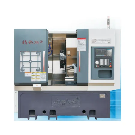
Jingfusi has been producing high quality Turning and Milling Combined Machine for many years and is one of the professional Turning and Milling Combined Machine manufacturers and Suppliers in China. Welcome to inquiry us at manager@jfscnc.com.


